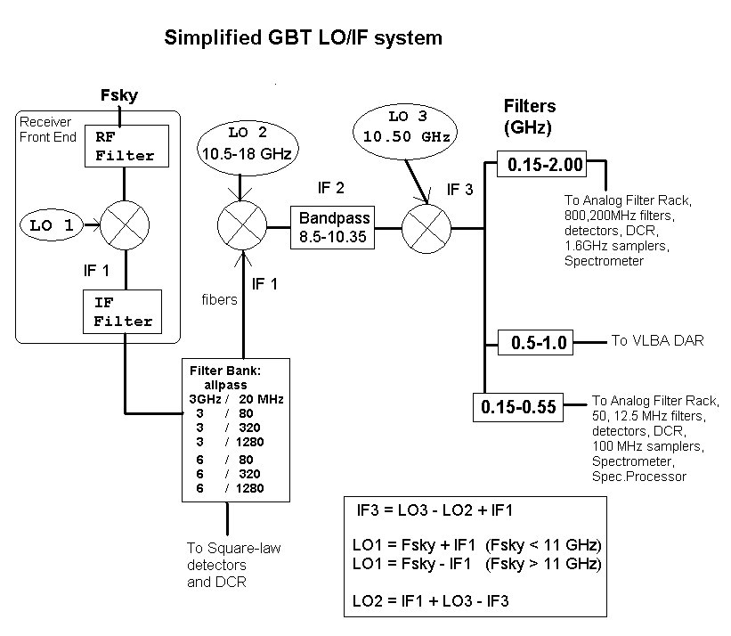
Appendix: GBT LO/IF System
The main frequency conversions are illustrated in the
following diagram.
Jump to: Prescription: How to select the LOs
 |
- Choices of RF and IF Filters are given in Table 1.
- The filter bank can be used to provide RFI protection
and to select the desired bandwidth for continuum observations.
- Use the "Fsky<11GHz" case for X-band and lower frequency receivers.
- Use the "Fsky>11GHz" case for KU-band and higher.
- (The frequency ranges of the X-band and KU-band overlap, so one cannot use a specific frequency to discriminate.)
|
Table 1 gives the choices for RF and IF bandpass filters available
for each receiver.
Table 1: Receiver Bandpasses and LOs |
Receiver
(band (GHz)) |
RF Bandpass (GHz) |
IF1 Equation |
LO1 Range (GHz) |
IF1
(Center)
(GHz) |
IF1 Bandpass (GHz) |
| Prime Focus 1 |
0.290 - 0.395
0.385 - 0.520
0.510 - 0.690
0.680 - 0.920 |
IF1 = LO1 - Fsky |
1.36 - 2.00
(1.0 Hz) |
1.08 |
bw=0.240
bw=0.080
bw=0.040
bw=0.020 |
| Prime Focus 2 |
0.910 - 1.230
|
IF1 = LO1 - Fsky |
1.99 - 2.31
(1.0 Hz) |
1.50 |
bw=0.240
bw=0.080
bw=0.040
bw=0.020 |
1-2 GHz
(1.15-1.73) |
1.10 - 1.80
1.10 - 1.45
1.30 - 1.45
1.60 - 1.75 |
IF1 = LO1 - Fsky |
4.15 - 4.73
(1.0 Hz) |
3.00 |
2.6 - 3.4 |
2-3 GHz
(1.73-2.60) |
1.68 - 2.65
2.10 - 2.40 |
IF1 = LO1 - Fsky |
7.73 - 8.60
(1.0 Hz) |
6.00 |
5.5 - 6.5 |
4-6 GHz
(3.95-5.85) |
3.90 - 5.90
3.95 - 4.65
4.55 - 5.25
5.15 - 5.85 |
IF1 = LO1 - Fsky |
6.95 - 8.85
(1.0 Hz) |
3.00 |
2.0 - 4.0 |
8-10 GHz
(8.0-10.1) |
7.90 - 11.60 |
IF1 = LO1 - Fsky |
11.0 - 13.1
(1.0 Hz) |
3.00 |
1.80 - 4.20
2.75 - 3.25 |
12-15 GHz
(12.0-15.4) |
11.80 - 15.60 |
IF1 = Fsky - LO1 |
9.0 - 12.4
(1.0 Hz) |
3.00 |
1.25 - 4.75
2.75 - 3.25 |
18-22 Ghz
(18.0-22.5) |
18.00 - 22.50 |
IF1 = Fsky - LO1 |
12.0 - 16.5
(1.0 Hz) |
6.00 |
1.6 - 6.5 |
22-26 Ghz
(22.0-26.5) |
22.00 - 26.50 |
IF1 = Fsky - LO1 |
16.0 - 20.0
(1.0 Hz) |
6.00 |
3.1 - 8.5 |
40-50 GHz
(40.0-52.0) |
40.0 - 52.0 |
IF1 = Fsky - LO1 |
34 - 46
(4.0 Hz) |
6.00 |
4.0 - 8.0 |
Notes:
- Receiver:
- Receiver designation, followed by the nominal usable band in GHz.
- RF BandPass:
- This shows the choices of RF bandpass filter. In some cases the
filter admits frequencies outside the usable band as given in
column 1, but the performance in these fringe areas is
somewhat worse than in the usable band.
- IF1 Equation:
- Receivers for frequencies up to X-band (8-10 GHz) are net lower sideband,
and the higher frequency receivers operate as upper sideband, as shown in the table.
- LO1 Range:
- The Tuning range of the first LO is shown, followed by the
resolution of setting the frequency, in parentheses.
Note that for the 22.0-26.5 GHz receiver, the synthesizer output is
multiplied by 2 to get LO1; and for the 40-52 GHz receiver the
synthesizer output is multiplied by 4.
- IF1 Center:
- Nominal IF1 center frequency.
- IF1 Bandpass:
- Some receivers allow a choice of bandpass filters in the IF.
For the prime focus receivers, bandpasses are centered on 1.08 GHz.
How to select the LOs: a simple prescription.
- Select IF1 appropriate to the desired receiver, as listed in Table 1.
If you deviate from the nominal center IF1, make sure the band of interest
lies within the IF1 bandpass limits.
- For Fsky < 11 GHz (i.e., prime focus, L, S, and X bands), calculate LO1:
- For Fsky > 11 GHz (i.e, Ku, K, and Q bands), use:
- Note that the LO1 synthesizer setting is not the same as
LO1 itself in the cases of the 22-26 GHz and 40-50 GHz receivers.
For the 22-26 GHz receiver, set the LO1 synthesizer to HALF of
the desired LO1; for the 40-50 GHz receiver, set the synthesizer to
one fourth of the desired LO1.
- Select IF3 appropriate for the desired back end:
- Spectrometer: 0.8 < IF3 < 1.6 GHz
- Spectral Processor: 0.15 < IF3 < 0.5 GHz
- VLBA: 0.5 < IF3 < 1.0 GHz
- Calculate LO2 :
Using the CLEO Screens to set the LO and IFs
- LO MANAGER CLEO SCREEN:
- Unlock the screen!
- Click the button next to the desired receiver to connect it to LO1
- Type the desired sky frequency band center into the "F0" parameter.
- Select lower or upper sideband. For frequency <= 10 GHz choose "lower",
otherwise, "upper".
- Type in the IF1 value for desired receiver. Use values from the above table.
- Make sure frequency frame of reference is as desired.
- Adjust LO power (dbm) to give 5 volts as shown in the receiver screen.
- CONVERTER RACK CLEO SCREEN:
- Unlock the screen!
- Set LO2 according to the prescription given above: LO2 = IF1 + 10.5 - IF3 (GHz)
- Make sure output selection is right for desired back end.
